 |
||||
|
|
||||
| |
I have created this page to help those that are having issues with your mods. As our business has grown, so have the tech support issues we face. Many of you are e-mailing me and asking when new mods will be complete. That depends totally on the amount of time I have free to do experimentation and research. I cannot experiment and continue to develop mods everyone are asking for if I have to spend all my free time answering questions that are covered in the instructions we send. Please read the instructions we send thoroughly. The info on this page should cover all the issues you may encounter. I do realize there are times when an e-mail or phone call is necessary, but please read the instructions and the info on this page before e-mailing or calling us. Thanx, Monte Allums |
|
| DIY PEDAL MOD TROUBLE-SHOOTING INSTRUCTIONS |
|
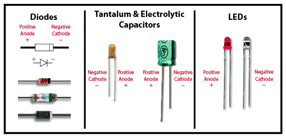
IMPORTANT: You must check the pedal after each component you change. You do not have to reassemble the pedal, just plug the power, input and output jacks in. Also, please don't completely take the pedal apart removing jacks, pots, etc. That is not necessary except on the Dyna, RAT and Daddy-O mods. Most pedals will not work If you completely disassemble them because the ground will been lifted from the circuit. Plug up a guitar and amp and make sure the pedal is functioning properly. Do not call or e-mail me if you perform all the component changes without checking after each component change, I will not be able to help you. If you check the pedal after each component change and there is a problem, you'll know exactly which component is causing the problem. If you perform component changes without checking the pedal after each component change, and you discover a problem, there is no way you or I can tell which component is causing the problem. SO, PLEASE CHECK THE PEDAL AFTER EACH COMPONENT CHANGE to make sure it is functioning properly! General Mod Issues: If the mod works initially for a while and then all of a sudden stops or starts giving erratic output then here's what I suggest. Take the back of the pedal off and look inside and see if there are any frayed or loose wires. If there are any wires that are frayed or hanging by a thread take and resolder the connection. Also take a close look at the solder joints you made on the components you changed. Are the joints spilling over into an adjacent pad? If so, soak it up with the desoldering braid I supply and resolder it. The key to soldering is to not add too much. Use only enough to make the connection. If the problem still exists try remelting the solder joint you made. This will sometimes fix a bad solder joint. Chip Adapter Mod Issues: Take the adapter out and put the original SIL opamp back in. Since the adapter assembly is socketed you don't have to unsolder from the pcb. If the problem goes away then the socket is soldered okay but the adapter probably has a bad solder pad somewhere. Could be a pad bleeding over into another or simply a bad joint. Try reheating the solder this will sometimes fix a bad joint. Also, cover the adapter assembly with electrical tape to eliminate the possibility that a short is causing the issue. Make sure you use some high powered glasses when checking the pads. They are tiny and hard to see. I use a pair of 2.50+ reading glasses you can buy anywhere. I also use some direct lighting to help me see. DOUBLE-CHECK UPON COMPLETION OF A MODDED PEDAL: I've gotten several e-mails lately where buyers have complained about not being happy with a mod. After a few e-mails back and forth we discovered that some components had been installed in the wrong places. Modding pedals is just like any other task one might do. A good mechanic always double-checks their work. Modding pedals should be no different. Once you've completed the entire mod it's vitally important that you get my instructions out and check off each component making sure that the right components are installed in the correct places and that the components with positive and negative sides are installed correctly. Read the instructions, ALL OF THEM! Most issues can be avoided by thoroughly reading the instructions. I have given you everything you need to successfully perform your mod. Take your time and read the instructions. It will save you time and frustration. .1uF AND .01uF CAPACITORS: Some kits includes both .1uF and .01uF Capacitors that look exactly the same. The .1uF has the number 104 written on it and the .01uF Capacitor has 103 written on it. Make sure the correct Capacitor is installed in the correct place. These Capacitors are very different in values and if installed in the wrong places will make the tone of the mod give the wrong results. SAVE THE COMPONENTS YOU REPLACE OR REMOVE: Use the plastic bag your kit came in to save the parts you remove from the pedal you are modding. If you are modding more than one pedal use a separate bag for each pedal. Write the name of the pedal on the bag. The parts will come in handy if you discover a problem at a later time and need to reinstall one of the components you removed. USE A 25 OR 30 WATT SOLDERING IRON: Using a higher wattage iron can damage the PCB and the components. And be very careful when moving the circuit board because it can fray the wires that are attached to it. Remove ALL the old solder! If the component doesn't easily come out DO NOT FORCE IT OUT! That will pull the pad trace up and that is a very bad thing. After removing the old solder if the component still doesn't want to come out, try heating the component with the soldering iron and gently remove it. Almost all pad traces are damaged by forcing a component out that has not had all the old solder removed. READ THE INSTRUCTIONS: I get a ton of e-mail. I spend more than one hour each day answering e-mail and almost 95% of the questions are covered in the instructions I include with your purchase. You should have received instructions in the form of an e-mail attachment sent to you after your purchase. I also send paper instructions along with the kit parts sent VIA snail mail. If you did not receive the e-mail attachment instructions it's because your ISP is filtering it as spam or a virus. You'll need to give us an alternative e-mail address along with proof of purchase. Either the PayPal Transaction ID or the e-mail address used to make the payment will suffice. DO NOT CALL ME OR E-MAIL ME IF YOU HAVEN'T THOROUGHLY READ THE INSTRUCTIONS! All your questions are covered in them. They include everything you need to do each mod. BOSS GE-7 WITH VINTAGE ACA ADAPTERS: There are two types of Boss GE-7 pedals on the market. The newer Boss GE-7s have only three 8-pin opamp chips. The older vintage Boss GE-7s have four 8-pin opamp chips. These older GE-7s use a different adapter (ACA) than the newer (PSA) pedals. If you are unsure which pedal you have, look on the front of the GE-7 and you will see a sticker. If the sticker says "USE BOSS ACA ADAPTER ONLY" then you have the older pedal (you can also tell by looking at the bottom of the pedal on the label). It's very important that you use only a Boss ACA Adapter or a new 9-Volt battery when testing the pedal. Using a regular Boss PSA Adapter the pedal will not get the correct voltage to the circuit and will cause audio problems that aren't really there. COMPONENT WON'T FIT HOLES: I love 1N4002 Rectifier Diodes as clippers in the gain circuit. But, unfortunately they're sometimes, depending on the PCB, too big to fit in the existing holes on the PCB. You'll need to use something to ream out the holes so they will fit. Amazon.com sells a Kronus Precision File Set that is perfect for enlarging the holes. It's $5.00 and works very well. Here's a link to the item you can buy right off Amazon's website (click here). I highly recommend it. Very high quality and will last.. It's perfect for this. But any fine tipped file will work. Be careful though. Filing too much can damage the PCB traces. REMOVE ALL OLD SOLDER: It's vitally important that all the old solder is removed BEFORE REMOVING THE COMPONENT TO BE MODDED. DO NOT FORCE THE OLD COMPONENT OUT! If the component doesn't come out easily then you haven't removed all the solder. Use the desoldering braid to remove the rest of the old solder BEFORE removing the old component. Forcing the component out without completely removing the solder will pull the trace off the PCB. This can possibly ruin your pedal! So, remove all the old solder before trying to remove the component to be modded. ITEMS WITH POSITIVE & NEGATIVE SIDES: Some of the components I supply have a positive and negative side. Make sure you install them correctly. The electronic instructions I send as an e-mail attachment will tell you exactly how these components are to be installed. Failure to follow these instructions can possibly fry the component. This is especially true with opamps and diodes. So, make sure you read the instructions thoroughly before installing them. The instructions (on diode replacement) mention a triangle that points in the positive direction on the PCB. You will NOT see this triangle until the old diode is removed. Use the pic below for clarification on diodes, tantalum caps and LEDs. REPLACING LEDS: Some of my mods include a replacement LED. They have a positive and negative side. If you look closely at the LED you will see what I like to call a Flag. When removing the old LED make a note of the Flag's orientation and install the replacement LED in the same direction as the old LED. If you install an LED and it doesn't work, simply turn the LED around and it will start working. All of the LEDs I sell are of the clear variety and it is impossible to tell what color it is. A good way to tell its color is to do this. Take a used 9-volt battery and drain it's voltage until it reads 2 to 3 volts on a multi-meter (I usually just place the battery in a pedal and leave it on until it drains the voltage down to 2 or 3 volts). Once the voltage is this low you can then use it to test the LED to see what color it is. DO NOT TEST THE LED WITH A NEW 9-VOLT BATTERY, IT WILL FRY THE LED RENDERING IT USELESS! I test all LEDs before I ship to see if they are faulty, so I'll know if you blew it or not. So please don't e-mail me asking for a Free replacement if you fry it. LOOSE WIRING: All pedals have wiring that is connected from the input, output, pots, switch and other components to the PCB. From the factory, some of these connections are not soldered well. Before starting your mods please check to see if they are securely attached. Some may need a little solder to firm up their connection. A little time spent up front can save you a ton of time trouble-shooting. Take the time to make sure those connections are firm and secure. Handle the PCB with care. Take your time. Most mistakes happen when we get in a hurry. NEWER DYNA COMPS: The newer MXR Dyna Comps use a new style of component PCB. The components are soldered on the front and back sides. This makes removing the old components tricky and difficult. The key with these pedals is to take your time and remove ALL the old solder thoroughly. Use the desoldering braid to completely remove the solder on the front and back sides. Again, let me stress, take your time and remove all the solder. On these newer Dyna Comps the jacks, pots and switch are attached directly to the PCB. You'll need to remove the nuts from the jacks, pots and switch before you can remove the PCB. |